This next post follows on nicely from the previous post where I wrote about VMware HCX Multi-Site Network Extension. Following on from discussions with colleagues currently sitting the HCX training course, as well as conversations/suggestions on Twitter the next logical lab to work on was a HCX Daisy-chained “L” shaped Network Extension. Okay, first things first, what is a Daisy-chain “L” shaped Network Extension? It is simply the extension of an already extended network. For example, your on-prem legacy environment is configured to extend a network via HCX into a new on-prem VCF environment. You are then also able to pair the HCX Cloud manager in in the VCF environment with another HCX Cloud manager, for example in VMware Cloud on AWS and extend the network from VCF into AWS – Legacy > VCF > VMC.
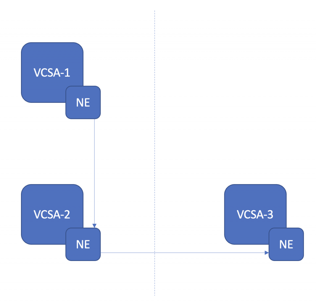
As always a picture paints a thousand words, the below shows at a logical level how I have configured this in the lab for testing. An NSX Segment in VCSA-1, extended to VCSA-2 with HCX. The L2E segmenet created in VCSA-2 is then extended into VCSA-3 with HCX (VCSA-3 is actually at a different physical location as well).
I already had the NSX segment in place from the previous post, so I set about stripping out previous HCX Service Mesh’s and disconnecting the HCX Connector paired with VCSA-1 from the HCX Cloud paired with VCSA-3. First site piaring for this lab in place, VCSA-1 > VCSA-2.

Second site pairing in place, VCSA-2 > VCSA-3.

As we can see the “middle site” VCSA-2 shows connectivity to VCSA-1 and VCSA-3. Also note, very subtly, the different icon for VCSA-1 from those of VCSA-2 and VCSA-3. It’s subtle, but I like it a quick and easy way to see that VCSA-2 and VCSA-3 are HCX Cloud destinations, where as VCSA-1 is a HCX Connector.
Confirmed from the VCSA-3 site that the HCX Manager see’s only the one site, that being VCSA-2.

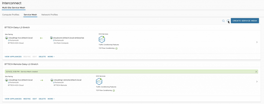
Next up, I need to configure some Service Mesh’s. As with the last post, in this lab I am only interested in testing Network Extension capabilities so the Service Mesh isn’t configured with any Hybrid Interconnect features – always conscious of resources in the lab :). That’s the first Service Mesh in from VCSA-1 to VCSA-2.

Now time for the second Service Mesh, from VCSA-2 to VCSA-3.
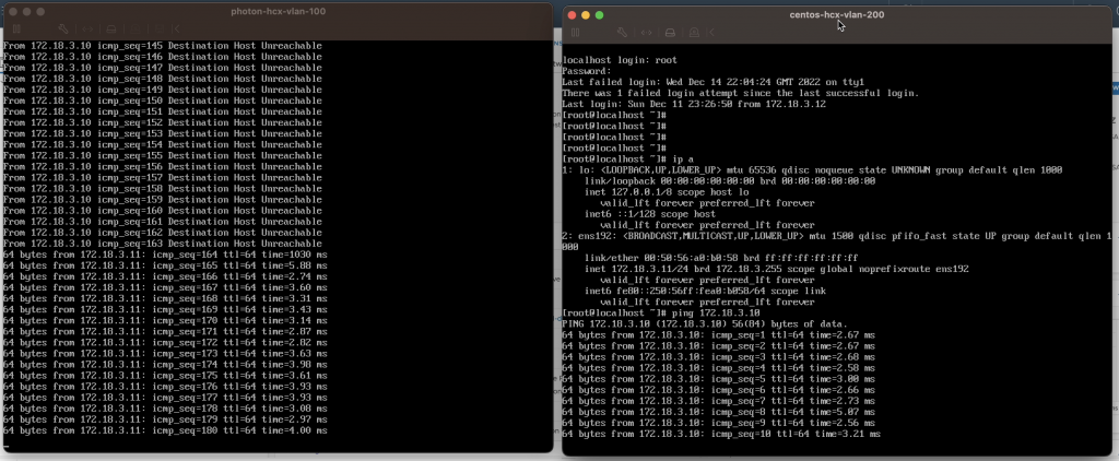
Following the deployment of both Service Mesh’s the step was to start extending the network. I first extended the NSX Segment from VCSA-1 to VCSA-2. With the help of a Photon VM in VCSA-1 (172.18.3.10) and a CentOS VM in VCSA-2 (172.18.3.11), connectivity was proven with the use of ping. The two VM’s could communicate with one another, proving the Network Extension.

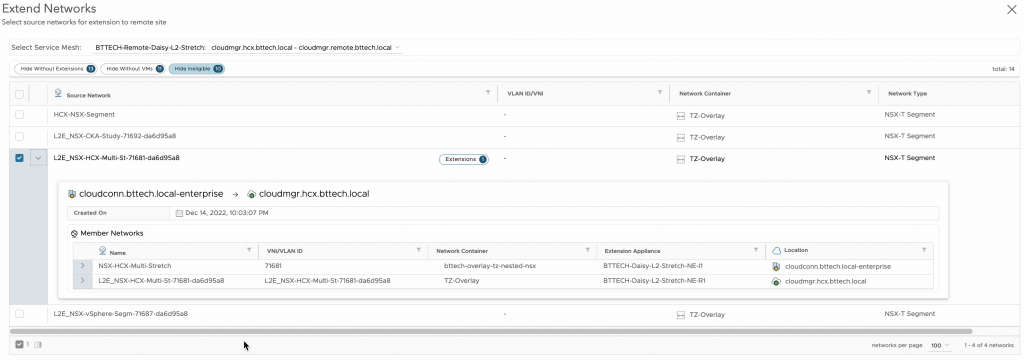
Next step, configure the Network Extension from VCSA-2 to VCSA-3 of the network that has been extended from VCSA-1. FYI when configuring the Network Extension it will look a little different in the wizard as HCX will report this as an extended network as you can see below.
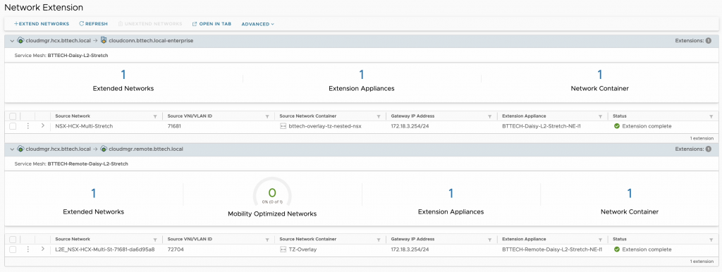
Once the extension has completed we should then have a view similar to the below, keeping in mind this lab is only being used at the moment for this testing purpose.
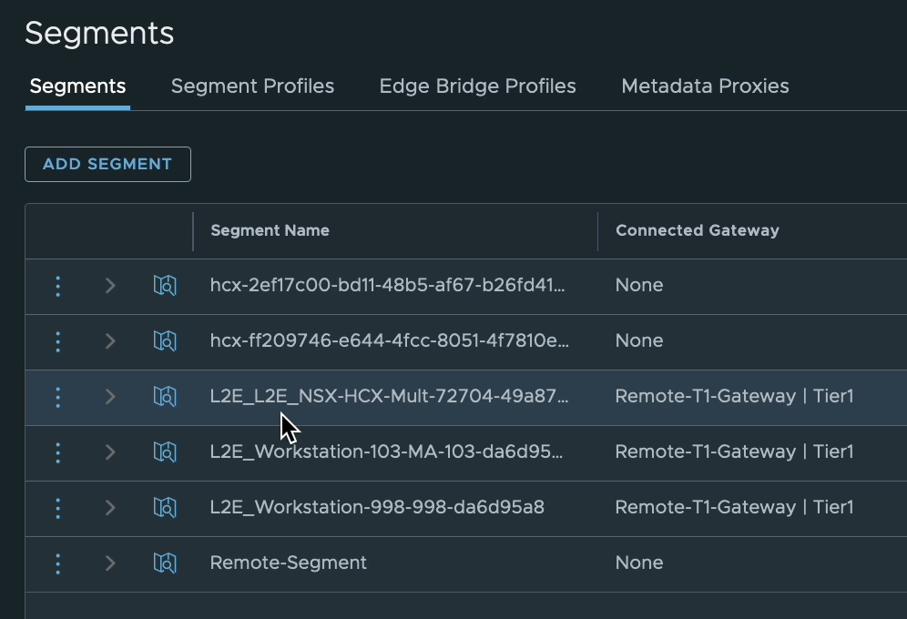
Point of interest, well I thought so, when HCX creates a segment on the Cloud side for a Network Extension the name is prefixed with “L2E” followed by a section of the segment name/port group name being extended followed by a random string. In this case as the extension was already an extended network, this lead to the prefix becoming “L2E_L2E”. Okay, perhaps not that interesting but I thought worth mentioning at least.
Using the same VMs as before I then proved connectivity with ping. The VMs running in VCSA-1 and VCSA-2 could communicate with the VM running in VCSA-3 (172.18.3.12) on the same L2. Pretty cool, considering that the communication from the VM in VCSA-1 was running through/reliant on the Service Mesh and Network Extension in VCSA-2.
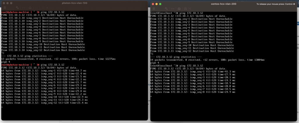
Before I powered down the lab, I had one more thought, then I had to test it just to see. The original network resides in VCSA-1, but what would happen if for some reason the connectivity out of the site with VCSA-1 failed and that Network Extension tunnel dropped. Would the VM in running in VCSA-2 still be able to communicate with the VM running in VCSA-3? I assumed yes, as they are on the same broadcast domain but I wouldn’t be able to get to anything external as the VM wouldn’t be able to reach the gateway. I simulated this by simply powering down the NE appliance in VCSA-2 for the Network Extension tunnel between VCSA-1 and VCSA-2. Assumption confirmed.
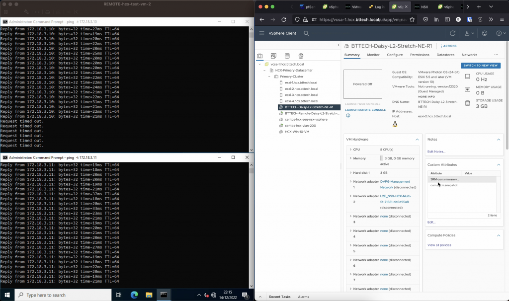
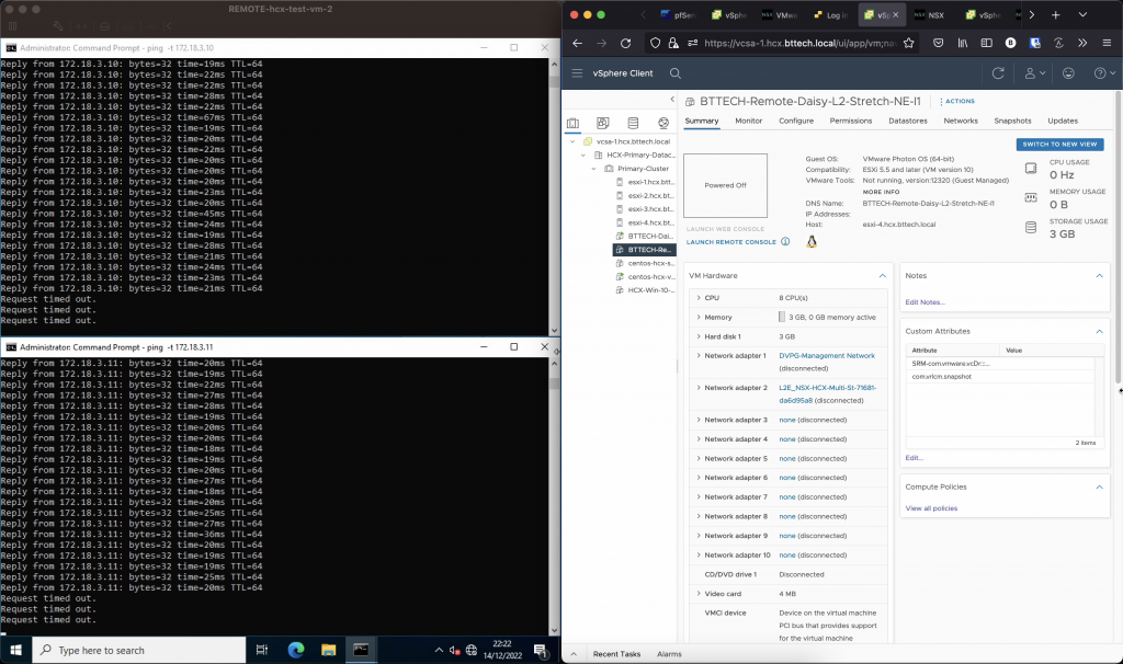
One more final test, while “in Rome”. I powered down the NE appliance in VCSA-2 running the tunnel between VCSA-2 and VCSA-3 (after powering up the other NE appliance again), as expected it broke communication from the VM running in VCSA-3 to both the VMs running in VCSA-1 and VCSA-2.
If you have a use case for this in production, be sure to review any restrictions and limitations around this typology – https://docs.vmware.com/en/VMware-HCX/4.5/hcx-user-guide/GUID-DBDB4D1B-60B6-4D16-936B-4AC632606909.html


