
It’s been a little while since my last post, with lots going on in and out of work and making the most of the sun finally arriving!
One of the topics I have been working on a lot of late is VMware Cloud on AWS, talking a lot about the extension of networks into the VMC SDDC while migration activities are carried out.
Now, I am a massive fan of HCX and all that it offers especially the ease of configuring a network extension from your old legacy environment into VMware Cloud on AWS! There are though some requirements that can stop you making use of the network extension capabilities of HCX, one being the use of vSphere Standard switches in your legacy environment. HCX requires the networks you wish to extend to be configured on a vSphere Distributed switch, we cannot extend a network that is configured on a vSphere Standard switch.
How then, would you go about extending your network for the migration window in this scenario? That’s where the L2VPN capabilities of NSX will come into play. What I want to discuss in this article, isn’t the process for the enablement of a L2VPN in VMware Cloud on AWS, but more the nuances and learning that I have had when configuring the NSX Autonomous Edge appliances required on prem. For this configuring I struggled to find the documentation I wanted, so I wanted to share what I have been able to determine.
I’m sure many of you reading this will have the same thought process as me and wish to avoid any single points of failure. To that end, enabling NSX Autonomous Edge HA appliances on prem for me was key. As mentioned I really struggled to find the documentation I wanted when deploying the NSX Autonomous Edge, so when I reached the point of attaching the vNICs to port groups as shown in the below screenshot, I wasn’t sure what “Network 1”, “Network 2”…… etc. related too.
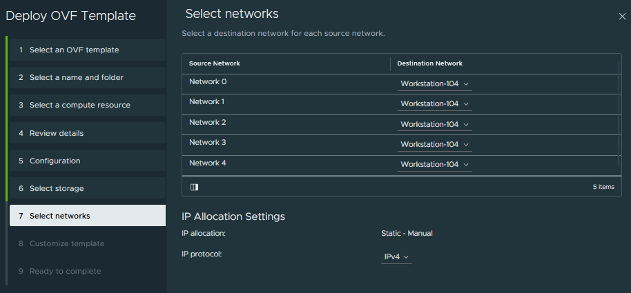
After some testing the below table indicates the mappings that I have been to ascertain from documentation and conversations with NSX colleagues.
| vNIC | Purpose |
| Network 0 (eth0) | Management connection |
| Network 1 (eht1) | Uplink interface |
| Network 2 (eth2) | Trunk port to be used for extended networks |
| Network 3 (eth3) | HA interface |
| Network 4 (eth4) | I am not sure on this one, Welcome input here if anyone is aware of the purpose for this interface. |
It then took me a long time, far to long to be honest, to work out how to configure the uplink interface, which to add a little more confusion for me is titled “External” in the OVA configuration. After some trial and error testing connectivity into the SDDC I now understand how this configuration string is expected. In fairness to the notes in the deployment, this is explained, I just couldn’t wrap my head around this. The configuration string required is as below <Vlan Id[0~4091]>,<Exit Interface>,<IP Address>,<PrefixLength>.
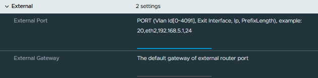
In my environment, the uplink interface was connected to a VLAN configured port group so there was no need for me to specify so I specified this as “0”. This made my external port configuration the following 0,eth1,10.10.20.138,26.
Next up was the configuration for the HA interface, once I had worked out the above this was simple enough as it follows the same logic.
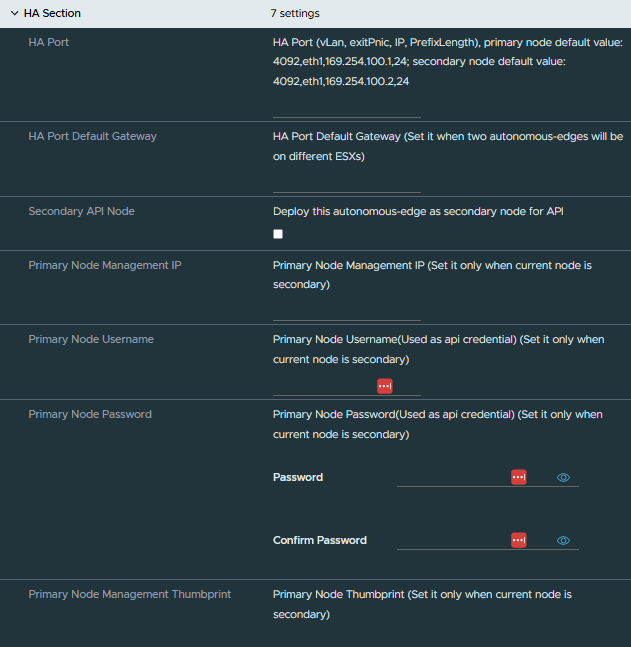
I have created a separate portgroup for the HA communication, my configuration for this interface was 0,eth3,192.168.1.1,24. After the population of the HA port details, no other information was needed for the primary node.
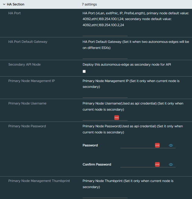
Once the first NSX Autonomous Edge was up and running it was time to move onto the next NSX Autonomous Edge deployment for the HA pair. This OVA configuration is slightly different to the first, for example on the secondary node we do not explicitly configure an uplink interface. The details for the uplink interface are synced with the primary node once the two are paired. We do though, need to configure the HA interface and select the following options in the HA section of the OVA deployment.
- Secondary API Node – this needs to be enabled
- Primary Node Management IP
- Primary Node Username
- Primary Node Password
- Primary Node Management Thumbprint
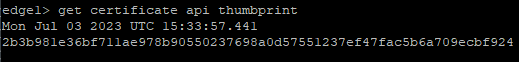
To collect the thumbprint from the primary node, I completed this by connecting to the primary node over SSH and running the following command get certificate api thumbprint which provided the required output.
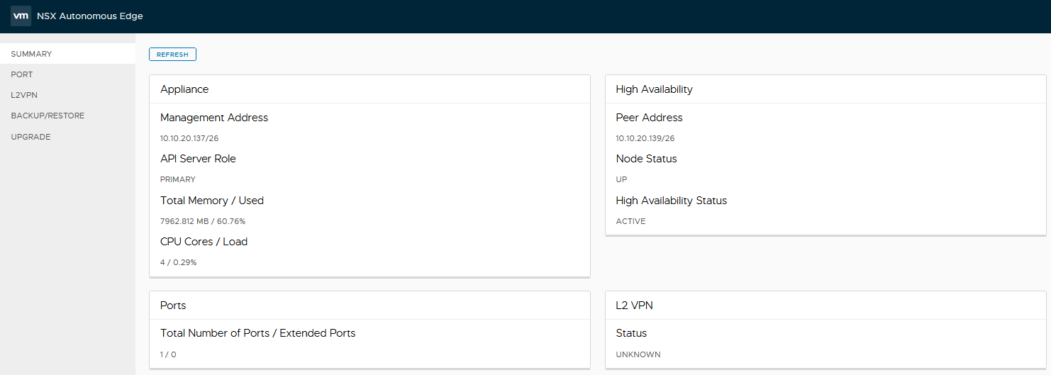
Providing all is well with the configuration and networking, once the secondary has been powered up and the two NSX Autonomous Edge appliances connected to each other we can see in the primary that the secondary has connected based on the high availability widget.
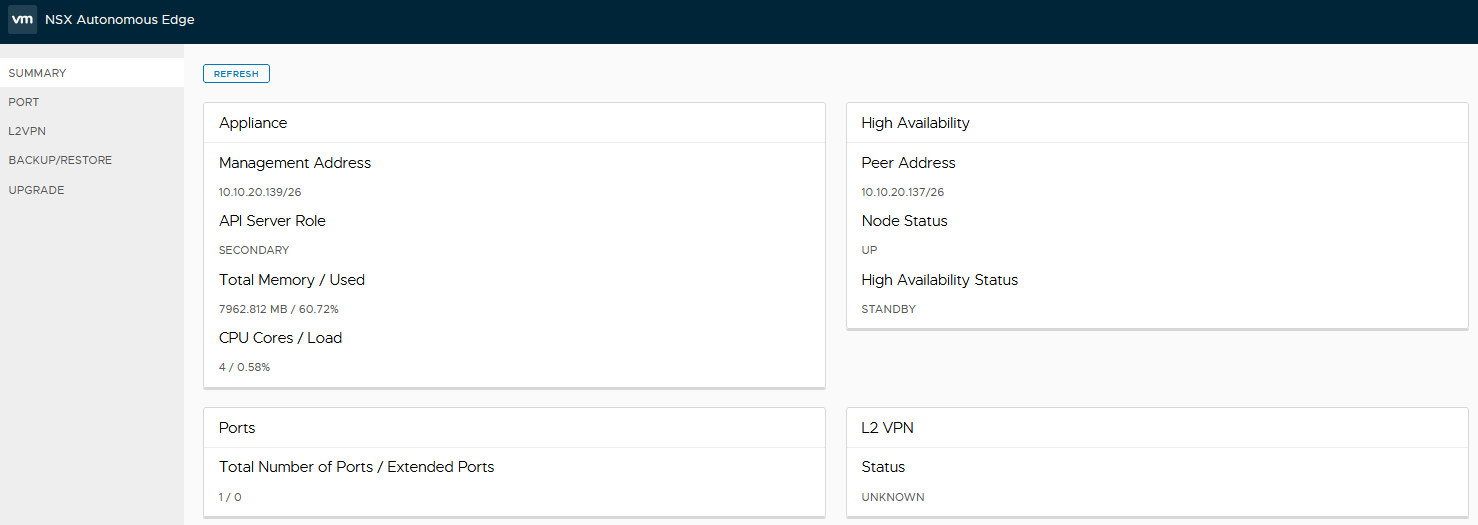
The high availability widget on the secondary node reports as the standby node.
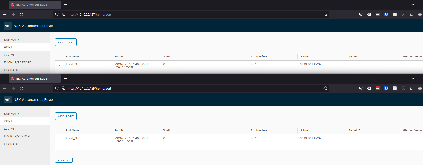
What’s interesting, when looking at the secondary edge we can see the uplink interface (named lrport_0) configured on here now as well within the ports section. It’s got the same IP though, how’s this work? Same IP, two different nodes, we know that leads to bad things, the below screenshot shows the ports on both nodes, top window being the primary node, the bottom window being the secondary node.
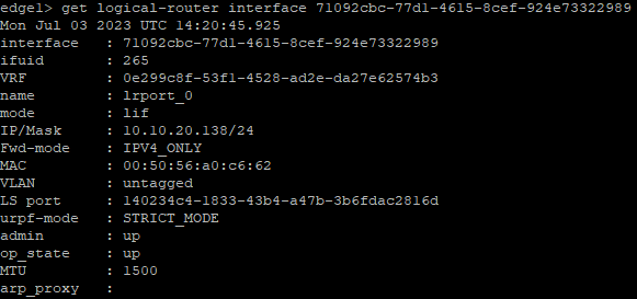
Let’s take a look at the appliances via the command line, now things start to make a little more sense. I first ran the following command get logical-router interface, this listed all the interfaces on the edge, looking for the interface named “lrport_0”. I then took the interface ID and amended the command to the following get logical-router interface <interface ID> in my case get logical-router interface 71092cbc-77d1-4615-8cef-924e73322989.
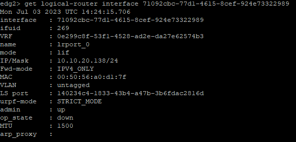
Run the same commands on the secondary node shows the below output. As you can see on the secondary node the admin status of the interface is up matching that of the primary node. The operational state (op_state) is down though, confirming for us that the IP is only active on the primary node.
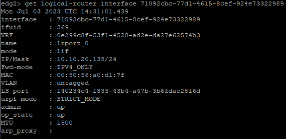
If I powered off the primary node, we can see in the summary view now that the HA status has changed to active.

The the commands on the secondary node again we can now see as well the op_state of the uplink interface has moved to up.


Pingback: L2 Network Extension via NSX Autonomous Edge - BTTECH Blog